Read this Thread
Thread Gage Basics – Go / No Go Acceptance
The basic concept of a thread plug is to provide a quick inspection for machinists and quality inspectors to verify that the threads are within the accepted tolerance so that it interacts with the mating part correctly. This verification would be preformed by threading the Go thread gage to the full depth of the feature without restriction; followed by the non-acceptance of the No-Go plug gage.
What may be a surprise to many is that there are cases when a threaded hole accepts the No-Go thread gage but not the Go gage. To fully understand how this is possible you must understand the difference between a Go and No-Go thread gage and how each of them interacts with the threaded feature.
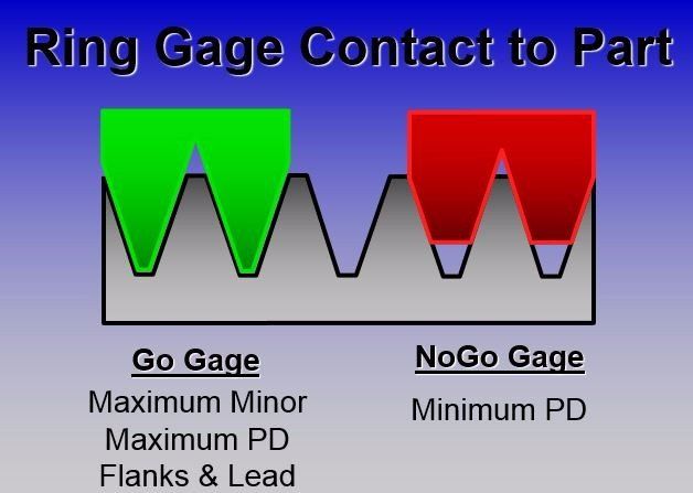
Let’s start with the Go member of any thread gage. This side of the plug gage is tasked with measuring the minimum major diameter, the minimum pitch diameter and the flanks and leads of the thread form. Like the No-Go side, the Go never checks the minor diameter of the thread feature. This check is preformed by another means such as a pin gage or dial bore gage.
The No-Go side of the thread gage preforms a check on the only the Pitch Diameter, verifying that it does not exceed the maximum condition. In this case the major diameter is not being checked. For this reason, if measured, the user will find that the OD of a No-Go thread gage is smaller than the OD of a Go thread gage. The reason behind this is because the No-Go plug is not tasked with checking the deepest points of the thread. This is verified by the Go gage only.
If the hole accepts the No-Go gage but not the Go gage, this is generally because the tips of the cutting tool have been worn or chipped causing the depth to be too shallow. In this case, the machinist will usually assume the thread feature needs to be opened more and make an adjustment to cut the thread larger. However, if the tip of the thread cutting tool has worn, compensating the cutter will lead to overcutting the thread pitch diameter. And since the No-Go thread gage only verifies the thread pitch diameter, it is possible to have a condition where the part accepts the No-Go but not the Go.
For this reason, it is very important to check the hole with the No-Go gage and the Go gage every time an adjustment is made to cutter compensation. It should never be assumed that compensation be continually made until the Go thread gage is accepted; as this side of the gage is checking more features of the thread than the No-Go thread gage.
With the same principles as thread plugs, thread ring gages also work in the same fashion. The only difference here is that a Go thread ring is measuring the maximum minor diameter instead of the minimum major diameter. The major diameter is not measured with either the Go or No-Go ring. That is measured with a separate gage such as an OD micrometer. Like the No-Go thread plug, the No-Go thread ring is only verifying that the pitch diameter is within allowable limits.
Again, the scenario of the part accepting the No-Go but not the Go gage is also possible with thread ring gages just as in the case of the thread plugs.
It is important to mention that thread gage fits are called out in two ways. For the Go side the fit is defined as “free and easy”. Although this can be interpreted differently depending on the user, the rule of thumb is that the gage should go in or over without obstruction. In the case if a thread ring this means that the gage should spin on without force. If your gage takes a measure of force to check the feature, this will cause the gage to wear out prematurely.
In the case of the No-Go thread gage, the most common misconception is that it should not enter or travel over the thread feature at all. In other words, it should “Not Go” at all. This is one of the largest areas of debate between machinists and quality inspectors.
According to the national thread standards, the no go can be allowed up to but not exceeding three full threads for standard gages or two full threads for metric thread gages prior to feeling a definite drag. In theory, you could travel the length of the thread with a metric No-Go thread gage providing you feel a drag after the second full turn.
There are exceptions to the rules for No-Go thread gages such as part materials. If the part being manufactured is of ductile material, or softer than the gage being used, there may not be any allowance for the gage to engage at all. This is also the case with short thread spans. If your thread length is only three or four threads long, you would not want to use the two turns or three turn allowance.
In the end, the thread standards allow the user to have a certain number of turns as a maximum condition for No-Go gage unless the product dictates you should reduce that because of the thread length or material.
Due to the nature of threads and the amount of geometry involved in creating them correctly, it can be beneficial to manufacturing companies to offer thread specific training to both machinists and quality personnel.
All your employees having the same understanding of what makes a proper thread can save your company the head aches and costs associated with bad parts.